In the last post we got a general idea of what the drive train is and what it is made up of. This post will discuss some of the challenges we face that will help determine the final design of the drive train.
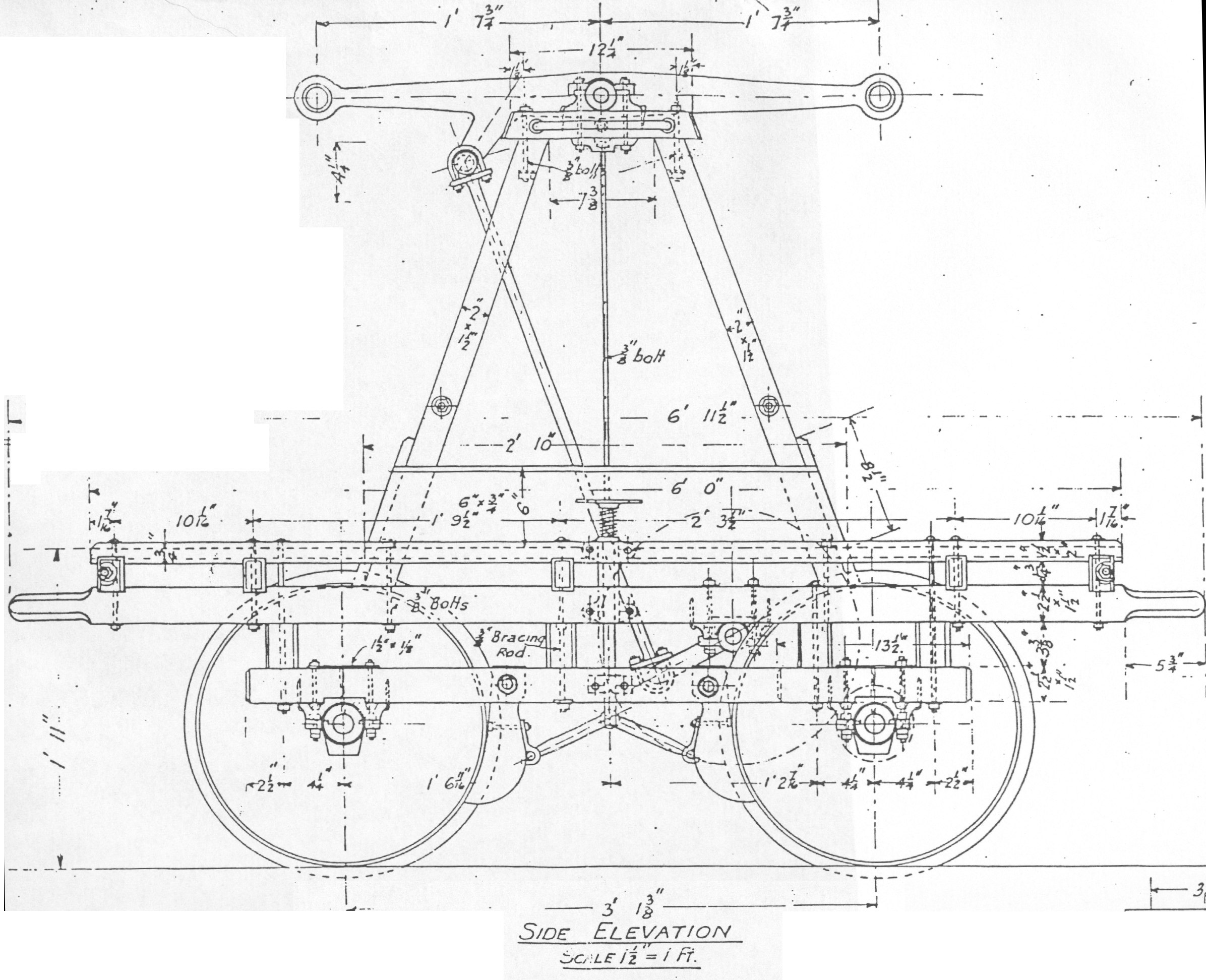
Again, the drive train will turn human up-and-down motion (from people pushing up and down on the pump lever) into rotational motion that will travel to the wheels. A system this can be compared to is a person riding a bicycle. In the case of the hand car the leg will be the pump lever and connecting rod. The bicycle pedal and crank arm will be the crank of the hand car. Using this model we have transformed up-and-down human motion into rotational motion. But a bicycle crank powers a sprocket, which drives a chain. In our case we will connect a drive shaft onto the crank parallel with the rotational axis of the crank. Picture the bicycle again and replace the left-side pedal with a shaft perpendicular to the bicycle. Actually just take a look at this diagram of a hand car. Notice the crank connecting to the crown wheel, this is what we will do, except the crown wheel will be facing the front of the vehicle. The axis of rotation will be in line with the direction of motion of the hand car.
Another issue arises in bracing all these components. We have some ideas for that so stay tuned.
Subscribe to:
Post Comments (Atom)

No comments:
Post a Comment