Tuesday, June 5, 2007
Still working It
Hola, Capt. Shit here. Just wanted to keep everyone updated on our progress. We are finalizing the specifics of our design and getting some prep-work in. We have set a timeline to have the base car completed by the 4th of July. We need to complete brake-work and base platform things this week. Parts we are looking for: Old tires, (for suspension), cable (for brake line) and sheets of metal (for bracket welds). There are more but I don't want to bore you. We will be posting some new 3D sketches of the car soon. Sit tight.
Thursday, April 5, 2007
Word Up
Just got word back from the DMV (Department of Mutant Vehicles from Burningman). Beacause our vehicle is human powered, it doesn't need to be registered. NO RULES MAN!!!!!!!!!!!!!!
Wednesday, April 4, 2007
Dimensioning and the Golden Ratio
In dimensioning and trying to find the size that will fit our needs we began by choosing random numbers. These were from what we felt would be the proper size. In a projects, such as this, incorporating meaning into every detail adds to the value and beauty of the finished product. Faced with numbers representing a vehicle's dimensions we incorporated the Golden Ratio. Because the ratio is not a whole number, it is really hard to get whole numbers to be in the exact Golden Ratio. So we end up rounding up or down. For instance the length of the base of the bottom platform will be 13. The height of the pyramid from the center of the base to the tip-top will be 21, 21/13 = 1.615. This is very close to the Golden Ratio of 1.618... The width of the base platform will be 8 feet, 13/8 = 1.625. Not as close, but still close. Applying this to other dimension, like the height of the second level, we will see the ratio appear in a number of places. If we choose 8 feet as the height, that would divide the total height into 8 foot and 13 foot sections. At 8 feet, the dimensions the pyramid legs enclose around the second platform are length 8 feet and width 5 feet, 8/5 = 1.6. A little further away but still close. If we decide to make a third smaller platform and put this 8 feet above the 2nd platform (dividing the height from the 2nd platform to the top, 13 feet, into 8 foot and 5 foot sections) we find the 3rd platform to be 3 feet long by 2 feet wide, 3/2 = 1.5. We're getting a little further out but a funny thing happens when we take a closer look at the numbers we have for our dimensions:
2, 3, 5, 8, 13, and 21. Does this number sequence look familiar to you?
It is a Fibonacci Sequence. The Fibonacci sequence is a set of infinite numbers, where each number is the result of adding the two numbers previous to it together. 2+3=5, 3+5=8,5+8=13 8+13=21... Check out the links because it's fascinating math.
Saturday, March 17, 2007
The Latest
We got an email from Lady Bee, burner name, that we were not accepted for the burning man art grant. A slight let down, but we push on. They did mention that our piece made it to the final round and had some encouraging words for us. Since then, our designing has made some significant progress and we have established teams throughout the USA to construct parts of the vehicle to be brought together in the northern desert of Nevada. The teams are located in San Francisco, Tuscon, Chicago and New York.
We are also working on a new look for the vehicle, instead of the old boxy aesthetic. The new design is based off of the great pyramids of Giza. This will give the structure more strength and will allow us to trade off for lighter materials. The upper deck structure will be constructed in Tuscon. The dimensions and technique are still in arbitration. We are beginning to look at bamboo and lashings. Bamboo is known for its high strength to weight ratio and it is also a renewable resource, I think.
We also are working on designing the vehicle so it is up to code and meets burning man's guidelines and standards. This will involve assuring them that the vehicle is safe, mechanically sound and is lit properly. We will have to apply for two licenses for day and night time playa cruising.
Below you may view our new design. Note: the dimensions are not to scale. it should be longer and more rectangular.

Thursday, March 8, 2007
Acquiring New Parts
Last weekend was spent in Maine searching for parts and pieces for the project. The search was for materials for the base structure, which will hold the axles together and which we will will build upon. And also sprockets and supports. View the pictures of the sprockets on the Flickr link below. There you will also see pictures of the wood pieces that will be used for the structure base, along with pictures of the mill they were cut from. The whole process to produce the timber beams could be considered eco-friendly. The tree the wood came from was selectively cut, unlike conventional clear cutting practices. The transportation from the wood lot to the mill was less than a mile. I did drive the wood to down to NYC but that I was doing anyway. Below is a video of pops hauling out the wood to put in the truck. In all honesty, this method is not very eco-friendly...but it is fun to watch.
Friday, February 23, 2007
Proposal In
The proposal to our burning man art project has been submitted. This is it...the text of it anyway. All pictures that we used in the proposal can be seen on the flickr page. Check it out...see below. In the process of writing the proposal we had to put ideas for the major components down on paper. These are or will be posted to the flickr page. I will do that now. See you soon.
Sunday, February 11, 2007
At all Costs
Wednesday, February 7, 2007
The Wheels In the Sky
We need to start sizing things up. Because we will be dealing with one gear, similar to a fixed gear bike, we have to figure out a comfortable speed. There will be an average speed we will want to attain while traveling. It can't be too fast and dangerous and it can't be too slow either. The vehicle speed will be directly proportional to the speed the pump lever will be pumped. This also has it's limits concerning speed. People can only pump so fast. So how do we design for both? It all has to do with the gearing where the drive shaft meets the rear axle at the differential.
The rear axle with the differential has a gear ratio of 5 to 1. That means for every 5 turns the shaft of the differential makes, the wheels turn once. That's a pretty low gearing. If there were a direct connection from the pump lever to the shaft of the differential, that would mean for every 5 times the pump lever goes up and down the wheel would make one rotation. The diameter of the wheels we have are 26 inches, which is about 7 feet in circumference. What would a comfortable speed be in which to pump? Maybe 2 seconds for one up-down motion, or cycle. With a direct connection, pumping at 2 seconds per cycle we would get a speed of 0.465 mph. Too slow. We need to add gears, but how do we calculate our gear ratio?
This spreadsheet calculates the gear ratio. I haven't figured out how to make it interactive, but I can make it so individuals can collaborate on it...aka use it, if I get there email. Let me know if you want to play around with it. The following is how it works.
First choose how fast you want to pump and the desired speed you wish the cart to travel at. These fields are not highlighted. A series of calculations are performed and it outputs a gear ratio. Next you can choose the size of the gear for the drive shaft (labeled 2), or choose the size of the gear for the shaft of the differential (labeled 3).
As you can see the gear size can be related to inches. So this combination of a roughly a 20 inch diameter gear on the drive shaft and a 1.5 inch diameter gear on the differential shaft will give us the desired speeds.
Saturday, January 27, 2007
View Pictures
Below in the links section you will find the flickr site we will store our pictures at. Right now there are some pictures of the front and rear axles, as well as drive shafts.
Friday, January 26, 2007
Drive Train: Cranking
In the last post we got a general idea of what the drive train is and what it is made up of. This post will discuss some of the challenges we face that will help determine the final design of the drive train.
Again, the drive train will turn human up-and-down motion (from people pushing up and down on the pump lever) into rotational motion that will travel to the wheels. A system this can be compared to is a person riding a bicycle. In the case of the hand car the leg will be the pump lever and connecting rod. The bicycle pedal and crank arm will be the crank of the hand car. Using this model we have transformed up-and-down human motion into rotational motion. But a bicycle crank powers a sprocket, which drives a chain. In our case we will connect a drive shaft onto the crank parallel with the rotational axis of the crank. Picture the bicycle again and replace the left-side pedal with a shaft perpendicular to the bicycle. Actually just take a look at this diagram of a hand car. Notice the crank connecting to the crown wheel, this is what we will do, except the crown wheel will be facing the front of the vehicle. The axis of rotation will be in line with the direction of motion of the hand car.
Another issue arises in bracing all these components. We have some ideas for that so stay tuned.
Wednesday, January 24, 2007
Plan of Attack: The Drive Train
After viewing the plans, which were linked in the last post, we can get a general idea of what we need to do. The most important part of this vehicle is the drive train. This is the system that will convert the human energy into mechanical. Once we have established a concept and design, we can begin gathering the pieces and parts to build it. Everything else will be built on top of the drive train. Let's define some parts.
1. The Pump Lever - This is the thing that looks like a see-saw in which the humans push up and down. It is one of the main components converting human power into mechanical power which will make the wheels go 'round and 'round.
2. The Connecting Rod - The connecting rod is connected to the pump lever and is used to turn the drive shaft. The arm is the major component that will change the up-and-down motion from the humans into rotational motion.
3. The Crank - The Crank connects the connecting rod to the drive shaft.
4. The Drive Shaft - The drive shaft carries the rotation motion to the rear axle.
5. Rear Axle - The rear axle is is connected to the drive shaft and distributes the rotational motion to the wheels.
These four components are key to powering the hand car. These are the basic parts. More will be introduce in the future that will aid in the vehicle's motion.
In the spirit of the Green Man, the car should incorporate as much recycled and reused material as possible. This will also save on cash. Another reason for this is because of the nature and size of the vehicle, certain parts must be extremely heavy duty. We don't have the resources or expertise to design and fabricate parts specially for the vehicle. This means more effort must be put in to find the right parts. We may also have to change our design because we don't have the exact part we want but we find something else similar.
Below is a rough sketch of the drive train:

The Vision
The vehicle will be very similar to the hand car seen in the links and pictures on the main page. We will expand to incorporate some new ideas. Of some of these ideas and modifications, many may be unrealistic and will not work with our scope of time and limited budget. Now is not the time to set limits.
The first big modification is for it be "road-worthy." Basically make it so we don't need tracks. A steering mechanism would be nice. Also a brake. The vehicle will need to carry at least 15 - 20 people. It will have to be a lot larger than the typical hand car. Below is an artist's rendition of the vehicle. There are posts in which lanterns are dangling from.

Some other ideas for carrying the large number of people are adding a trailer or a second story.
Beginning: Vision + Plan = Reality
This is the first post of the blog. I guess you have a idea of what this blog will be if you have studied the main page and link(s).
The ultimate goal will be achieved when this vision is turned into a reality. It is really hard sometimes but if the process can be broken down into steps and each step is treated as a small goal to be achieved, success is within reach, motivation is at hand, and the feeling of being overwhelmed will be deposited neatly in the shit-house.
The problem we face is a problem many face. When one has never heard or seen of such a thing, how do you build it? A technique we will use can be compared to a rap song, or a better example would be the Grey Album, by Danger Mouse (I think). The Grey album was basically all Jay-Z lyrics from the Black Album, mixed to music from the Beatles' White Album. So basically, use other peoples inventions and techniques and incorporate them into yours.
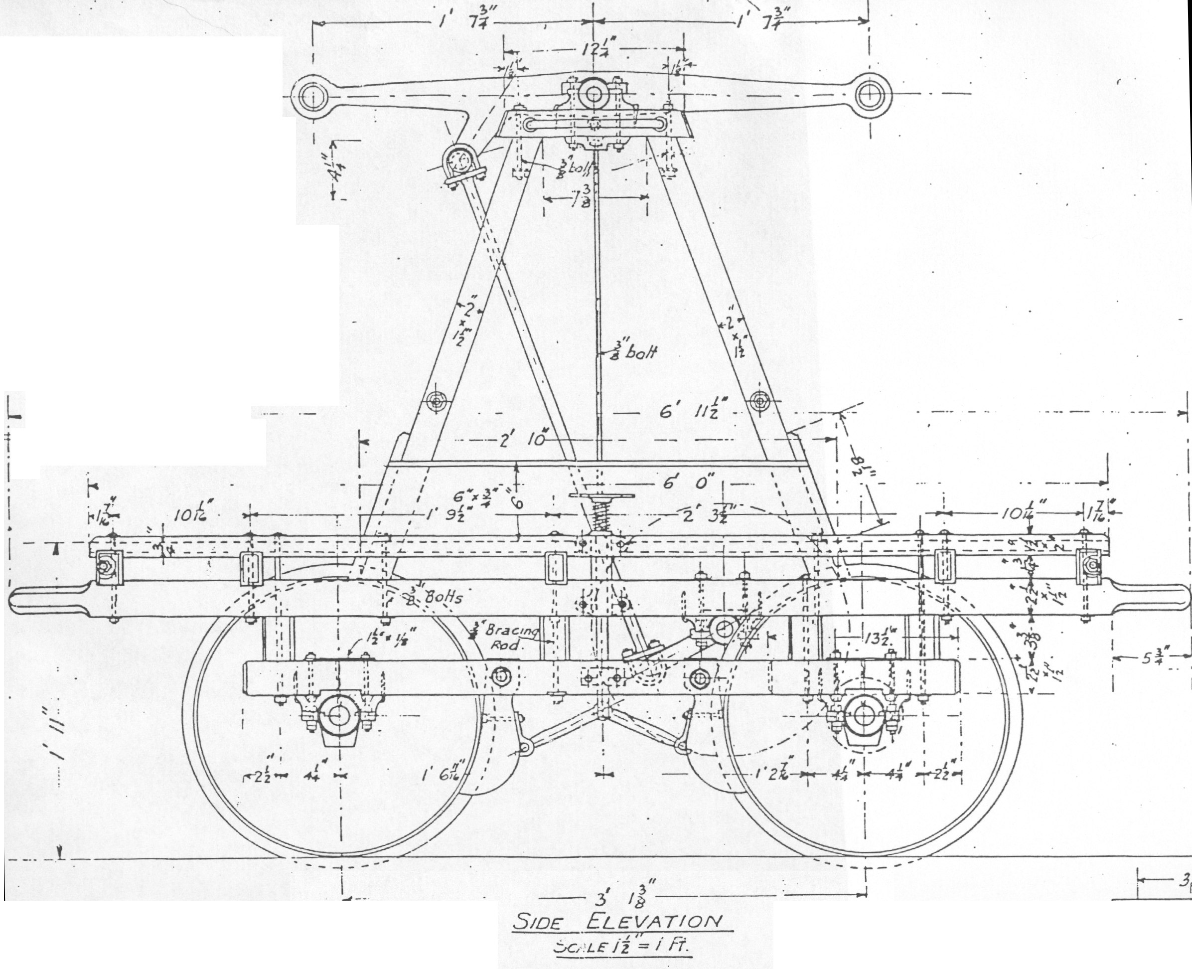
In regards to this hand car, we will obviously take the design of an original hand car and modify it for the road. Take a look at this link for Plans. This can be found in the link on the main page of this blog. Here you will find actual plans from an old time hand car. Download these jpgs and you will understand the workings of a hand car and how it works.
This is a good place to stop.
The ultimate goal will be achieved when this vision is turned into a reality. It is really hard sometimes but if the process can be broken down into steps and each step is treated as a small goal to be achieved, success is within reach, motivation is at hand, and the feeling of being overwhelmed will be deposited neatly in the shit-house.
The problem we face is a problem many face. When one has never heard or seen of such a thing, how do you build it? A technique we will use can be compared to a rap song, or a better example would be the Grey Album, by Danger Mouse (I think). The Grey album was basically all Jay-Z lyrics from the Black Album, mixed to music from the Beatles' White Album. So basically, use other peoples inventions and techniques and incorporate them into yours.
In regards to this hand car, we will obviously take the design of an original hand car and modify it for the road. Take a look at this link for Plans. This can be found in the link on the main page of this blog. Here you will find actual plans from an old time hand car. Download these jpgs and you will understand the workings of a hand car and how it works.
This is a good place to stop.
Subscribe to:
Comments (Atom)
